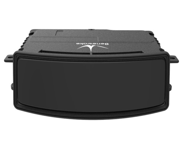
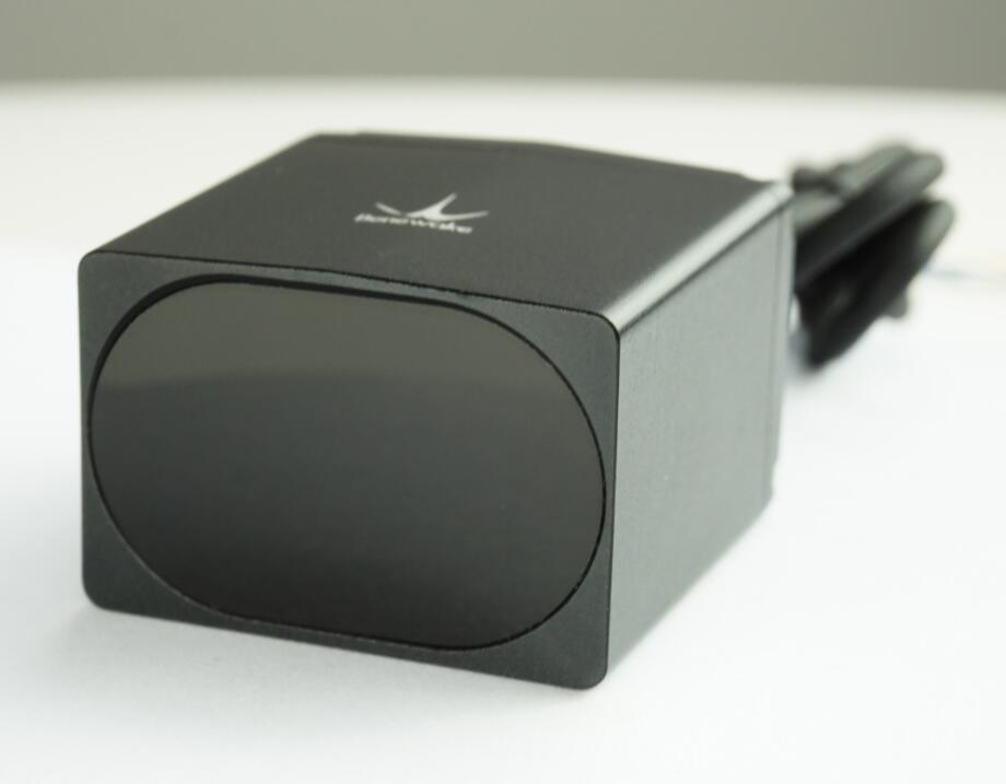
3D LiDAR 256 Lines Point Cloud Benewake AD2-S-X3 Long Range 350m for ADAS Autonomous Driving Truck – More Details


Sensors
3D LiDAR 256 Lines Point Cloud Benewake AD2-S-X3 Long Range 350m for ADAS Autonomous Driving Truck – More Details
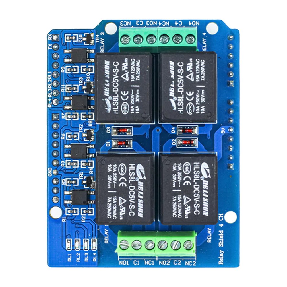
SB Components Ardi Relay HAT for UNO R3 Development Board Relay Shield Expansion for Arduino Uno, Mega, ArdiPi & Ardi32. More info
3D Camera 80×60 – Build Depth-Sensing Applications for Smart Buildings, Automation, Robotics, and more! It has an OpenNI-based SDK, C/C++ samples, Python samples, and ROS package. Details

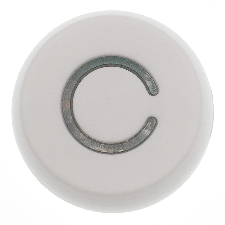
A Six-axis sensor can measure accelerometer value through the X, Y, and Z-axis and measure angular velocity through a gyroscope. This product can send the collected acceleration data to the mobile phone or gateway through the beacon broadcast. After the sale, we will also provide a testing app to help clients test and set sensor parameters, such as sensor name, data connection interval, connection range, etc. More info
Traffic light timing programs aim to develop further adaptive signal control technology (ASCT) to adapt programs to real-time traffic demands and thus reduce traffic congestion in urban areas. An effective ITS providing real-time information for decision-making algorithms is needed by the ASCT.
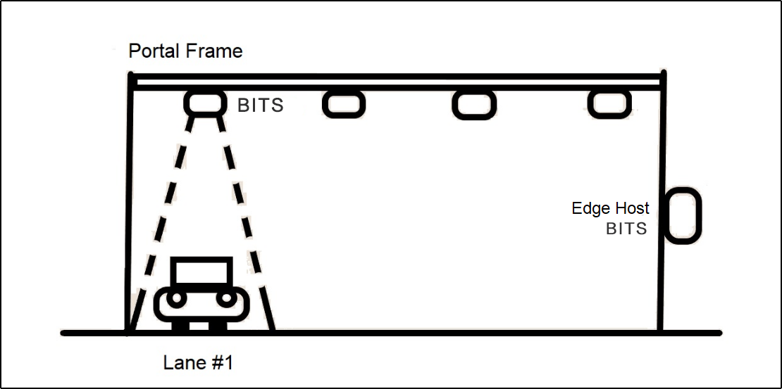
Benewake launched the BITS, the Benewake Intelligent Traffic System, to provide an effective traffic statistic collecting solution, which can effectively and accurately detect multiple types of traffic statistics, such as vehicle model (profile), vehicle speed, and vehicle height.
Based on Benewake’s single-point LiDAR, TF03, BITS consists of two parts: BITS-2A, collecting traffic statistics with two TF03s; BITS-C, the control board used to process data collected by BITS-2A.
This solution is based on the Benewake single-point ToF LiDAR and consists of three parts: the data acquisition unit, using the Benewake single-point long-range LiDAR, TF03; the main control board, used to collect and process LiDAR information and control output results, control LED display screen (can be omitted); mechanical structure, used to install and fix the entire program.
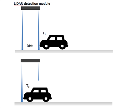
The two LiDARs are installed in the vertical ground direction and the tilt-to-ground (40 °) direction. The tilt LiDAR and the vertical LiDAR can detect the vehicle successively, calculate the trigger time difference between the two, and then calculate the vehicle’s driving speed. In addition, the data measured by the vertical LiDAR can restore the contour information of the vehicle. Finally, a neural network algorithm completes the model recognition.
Vehicle height information can be directly obtained by vertical LiDAR measurement. Next, the two LiDARs calculate the vehicle speed and the trigger time, which calculates the available vehicle speed. Finally, the neural network algorithm matches and identifies the original data collected by LiDAR.
After completing the recognition test, the main control board directly transmits the test results to the customer’s central control system through the data line. Transmission content includes statistics of vehicle models, vehicle height, vehicle length, vehicle speed, and several vehicle models.


Spot is a four-legged robot designed for indoor and outdoor operation. It has been the breeding ground for a new approach to dynamic robot control that brings true autonomy within reach.
Spot is electrically powered and hydraulically actuated. It senses its rough-terrain environment using LIDAR and stereo vision in conjunction with a suite of on-board sensors to maintain balance and negotiate rough terrain. It carries a 23 kg payload and operates for 45 minutes on a battery charge.
By Boston Dynamics
