
Tonybot is equipped with a sensor expansion kit so that you can carry out secondary development through Arduino programming. In addition, the detailed tutorials and open-source materials we provide can help you realize your great ideas! Details

Tonybot is equipped with a sensor expansion kit so that you can carry out secondary development through Arduino programming. In addition, the detailed tutorials and open-source materials we provide can help you realize your great ideas! Details
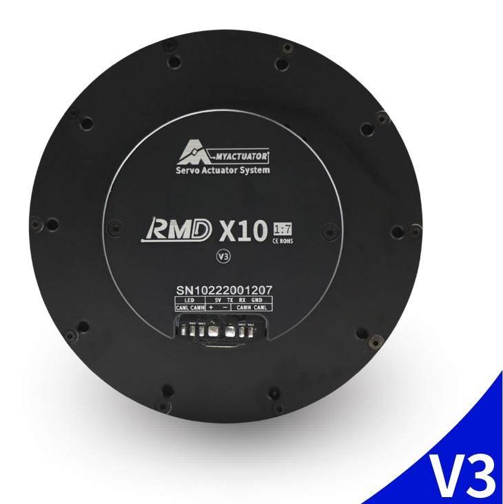
Precise rotation 1:7 makes control more precise. Provide diversified choices for customers in different fields. Support communication methods: CAN bus 32 BIT ARM: The drive adopts a 32-bit high-performance ARM chip—a high-precision planetary reducer. Precise rotation 1:7 makes control more precise. Provide diversified choices for customers in different fields. 32 BIT ARM: The drive adopts a 32-bit high-performance ARM chip. High-performance MOS-FET supports 48V voltage. Compact flat structure, powerful torque output. More Details
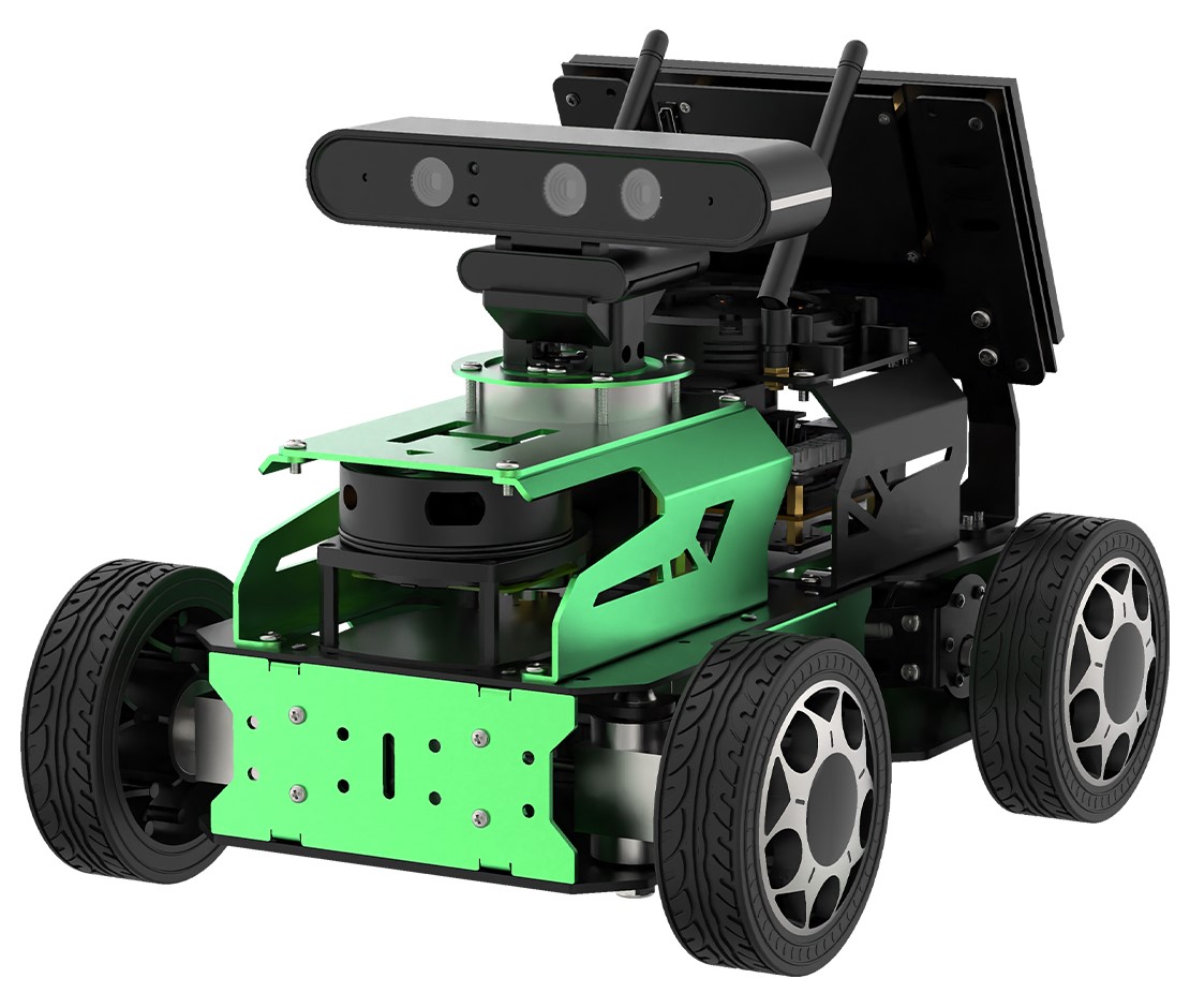
JetAcker is an entry-level ROS education robot powered by Jetson Nano. Featuring a Lidar, depth camera, and 7-inch LCD screen, JetAcker provides various functionalities, such as robot motion control, mapping and navigation, and human feature recognition. More Details